How can sensor interface design prevent unreliable readings in industrial products?
A pressure sensor can meet its specification while the finished product reports unreliable readings. Connect it through a longer cable, fit it beside a motor and power it from the production electronics, and the controller may see behaviour that never appeared on the bench.
Good sensor interface design accounts for the complete measurement path: the sensor, its supply, the wiring, the input electronics and the firmware interpreting the result. Accuracy depends on how those elements work together.
For manufacturers, getting that integration right can help avoid false alarms, unnecessary service visits and late design changes.
Why a good sensor can still produce unreliable readings
A sensor’s accuracy specification describes its performance under stated conditions. The finished product must also account for errors introduced by the electronics and installation around it.
Consider a refrigeration temperature sensor connected to a controller. Its output must reach the input circuit, be converted into a digital measurement and be translated into the correct temperature. Each stage needs to preserve the information the sensor provides.
Even a seemingly straightforward connection can need careful design. A sensor may struggle to drive the sampling input of an analogue-to-digital converter, or ADC. If the input has insufficient time to settle, the conversion can be wrong despite the sensor producing the expected voltage. The reference voltage and input range also influence the result.
Begin by defining the required accuracy of the complete product across its operating conditions. Then allocate an acceptable share of the error to the sensor, input components, reference and conversion process. This gives engineers a basis for choosing components and deciding where calibration is needed.
For a pump controller, the requirement might involve reliable pressure measurement while the motor starts and stops. For refrigeration equipment, it may involve maintaining useful accuracy across changes in ambient temperature. Those requirements are more informative than selecting a sensor by its headline accuracy alone.
Matching the sensor interface to the cable, controller and environment
Industrial sensor integration starts with choosing an interface that suits the application. Current, voltage and digital outputs each have useful strengths, alongside conditions that the product design must accommodate.
| Interface | Where it can be useful | What the design must address |
| Current, such as 4-20mA | Carrying process measurements over longer industrial cable runs. | Sufficient loop voltage for the transmitter, wiring and receiver; input accuracy and fault detection. |
| Voltage, such as 0-10V | Connecting sensors to compatible analogue controller inputs. | Ground references, input loading, cable noise and the permitted voltage range. |
| Digital, such as IO-Link | Transmitting measurements alongside supported configuration and diagnostic information. | Compatible hardware and protocol, cable limits, update timing and handling of communication faults. |
Current-loop guidance emphasises checking the voltage available after losses across the wiring and receiver. Digital systems such as IO-Link can provide additional diagnostic information, but still require a compatible implementation. The choice should follow the installation requirements.
Design the cabling and grounding with the electronics.
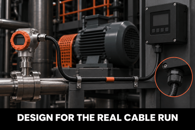
The production cable should be part of the design review. Specify its length, routing, connector arrangement and any shielding requirements, then consider the motors, relays and power wiring it will sit beside.
Ground references also need deliberate treatment. A difference between the sensor’s ground and the controller’s ground can appear as measurement error. Depending on the interface, differential measurement or isolation may help, but the circuit must remain within its specified electrical limits.
Record the intended grounding and shield connections in the installation documentation. This gives the product a defined arrangement that can be tested and reproduced.
Condition and protect the signal without losing useful information.
Sensor signal conditioning prepares the output for the controller. It may include amplification, filtering, excitation or conversion into a suitable input range.
For an analogue input, review the sensor output, filter and ADC together. A filter that reduces unwanted variation can also slow the response. The sampling arrangement must allow the signal to settle while still capturing changes the product needs to detect.
Input protection needs similar care. External connectors can expose electronics to electrical disturbances, but protection components also have characteristics that affect measurement performance. Leakage, capacitance and added resistance should be assessed alongside the protection they provide.
Make the firmware interpretation explicit.
A correctly received signal can still become an incorrect reading if the firmware uses the wrong range, units or calibration values.
For example, replacing a pressure transmitter with one covering a different measurement range requires the scaling to be reviewed. A familiar 4-20mA output does not tell the controller which pressure range the transmitter represents.
Define how the product identifies invalid readings, disconnected sensors and communication timeouts. If the last valid measurement is retained, the system should distinguish it from a fresh reading. The intended response should be documented and tested, including any effect on alarms or control functions.
Validating measurement performance before production

Validation should demonstrate the behaviour of the complete product in its intended configuration.
Begin with measurable acceptance criteria: accuracy across the required range, repeatability, response time and behaviour during relevant disturbances. Specify what is acceptable during start-up, supply variation and recovery from a sensor fault. Choose reference equipment with sufficient accuracy to judge those limits.
Use both controlled electrical inputs and the actual sensor. An electrical simulator helps isolate the performance of the controller input and firmware. Testing with the real sensor checks the complete path, including its supply, mounting and response to the quantity being measured.
For a pump product, test readings while the motor and switching loads operate. For a tank-level transmitter, include the intended cable lengths and supply conditions. For refrigeration equipment, examine measurement performance across relevant temperatures and compressor operating cycles.
Keep the production enclosure, connectors and wiring in these trials. Changes to the physical arrangement should trigger a review of whether earlier results still represent the finished product.
It is also useful to distinguish genuine signal changes from unwanted variation. Filtering can make a display look calmer while delaying a response the controller needs to make. Check both the reported value and the time taken to react.
Validate multiple units and retain the settings used during testing. Record sensor variants, firmware versions, calibration data and test results so that manufacturing has a clear reference.
This connects with designing calibration into the manufacturing process. Calibration can address defined measurement errors, while the wider design and validation process establishes how the product behaves across its intended conditions.
TAD’s industrial electronics work brings together sensing, input circuitry, embedded firmware, protection and testing. Reviewing those elements together gives manufacturers a practical route from a suitable sensor to a dependable finished product.
If you are developing a sensor-based product or revising one with inconsistent readings, talk to TAD about reviewing the complete measurement path before committing to production.
Click here to get in touch or here to read more.
‘Engineering Design, Imagine what could exist’
Got a web design question or mobile application need? Our in-house design agency, Bluebrick Studios, has you covered. Check out their site to find out how they can help you achieve your mission.
Frequently asked questions
What is sensor signal conditioning?
Sensor signal conditioning prepares a sensor’s output for measurement by a controller. Depending on the sensor, it can include amplification, filtering, providing an excitation supply, isolation or conversion into a suitable electrical range.
Why do sensor readings change after installation?
Installation can introduce different cable lengths, ground references, electrical interference, supply conditions and temperatures. The interface and firmware may respond differently under those conditions, even when the sensor itself is operating correctly.
Is 4-20mA better than 0-10V?
It depends on the application. A 4-20mA loop is often well suited to longer industrial cable runs, provided its voltage budget is sufficient. A 0-10V interface can suit compatible equipment where grounding, loading and noise are controlled. Neither removes the need to validate the complete system.